


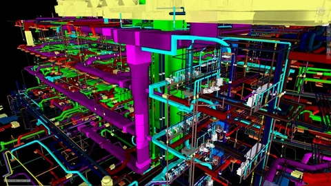
A high-rise mixed-use development enters the construction documentation phase with architectural and structural models approved. MEP BIM services systems are modeled in 3D, and clash detection software is available. As shop drawings progress, duct mains intersect beams, sprinkler lines compete with cable trays, and plant room access zones conflict with equipment clearances. Installation sequencing becomes complex, and coordination meetings intensify.
The project team invested in BIM tools and modeling standards. However, the model serves mainly as a visual reference. Interdisciplinary workflows lack defined ownership, LOD transitions vary between trades, and penetration approvals move forward without spatial validation across all systems.
Industry research indicates BIM can reduce project costs by up to 15% and construction time by 20%. Studies show early BIM clash detection can reduce design errors by more than 70% while significantly improving coordination efficiency. These results depend on disciplined execution rather than software availability.
A structured MEP Coordination Services transforms federated models into coordination engines. It integrates Scan to BIM inputs, AI-supported model validation, clash categorization, and fabrication-aligned detailing, delivering installation-ready geometry for architects, engineers, contractors and suppliers.
Section 1: Where MEP BIM Services Add the Most Value
MEP BIM Services create measurable impact during design validation, spatial coordination, prefabrication detailing, and field verification. They align MEPF systems with architectural and structural constraints while supporting code compliance, energy modeling and lifecycle asset data integration.
These Services connect schematic planning, detailed coordination, and as-built model validation with construct able installation data across all project stakeholders, enabling digital intent to translate into accurate field execution.
1. Design Development
During design development system loads, shaft capacities, and equipment footprints are validated using coordinated 3D models. Hydraulic calculations, external static pressure checks, and panel schedule alignment improve system performance and spatial feasibility before construction documentation advances.
- Validate duct sizing using airflow and pressure drop calculations
- Confirm pipe diameters through hydraulic modeling
- Check equipment maintenance zones against architectural layouts
- Align fire protection routing with structural framing
2. Coordination Phase
In this Phase federated BIM models integrate architectural, structural, and MEP trades. Clash matrices categorize plumbing to structural, mechanical to structural, and electrical to mechanical conflicts for systematic resolution.
- Run hard and soft clash detection in Navisworks
- Assign clash ownership by discipline
- Validate sleeve and penetration locations
- Coordinate plenum and shaft routing level-by-level
3. Prefabrication and Shop Drawing Development
At LOD 350–400, models shift toward fabrication readiness. Detailed fittings, slopes, hangers, and spool breakdowns align digital geometry with manufacturing workflows and off-site assembly.
- Generate spool drawings with dimensions
- Model hanger supports and trapeze systems
- Integrate fabrication standards into routing
- Extract quantity take-offs directly from models
4. Installation and Field Support
During construction coordinated models support sequencing, field verification, and retrofit validation using scan overlays and AI-assisted comparison tools.
- Overlay point cloud data for deviation analysis
- Update as-built conditions in central model
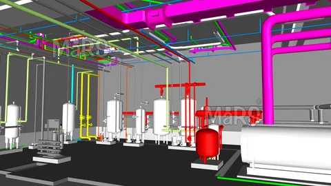
- Support plant room constructability reviews
- Validate system elevations before ceiling closure
Section 2: Core Workflows of Effective MEP BIM Services
Structured workflows convert modeling data into coordination intelligence, connecting Scan-to-BIM inputs, AI-supported validation, clash tracking dashboards, and fabrication-aligned documentation across project milestones.
1. Model Setup and Data Standards
Effective coordination begins with standardized templates for MEPF disciplines. Shared coordinates, origin alignment, naming conventions, and parameter mapping create a stable digital environment. LOD definitions from 100 to 400 guide model maturity across design phases.
Pain Point Addressed: Misaligned coordinates causing repeated penetration and sleeve adjustments.
2. Federated Model Creation and Clash Detection
Discipline models merge into a federated environment for spatial testing. AI-supported scan-to-BIM tools enhance accuracy in retrofit conditions. Clash reports categorize issues such as plumbing-to-structural flange conflicts and duct-to-beam intersections for prioritized resolution.
Pain Point Addressed: Congested plant rooms limiting equipment access and service routing.
3. Iterative Coordination Reviews
Weekly coordination meetings review clash dashboards, resolution progress, and updated models. Gatekeeper sessions track closed and active conflicts using documented approval workflows and digital issue logs.
Pain Point Addressed: Design modifications progressing without interdisciplinary validation.
4. Generating Coordination-Ready and Fabrication Ready Drawings
Building Validated models produce coordinated ceiling plans, riser diagrams, isometric drawings and panel schedules. Fabrication ready outputs integrate connection details, slopes and support spacing aligned with SMACNA, NFPA, and ASHRAE guidelines.
Pain Point Addressed: Shop drawing revisions triggered by incomplete system detailing.
Section 3: Making MEP BIM Services Work with Your Team
Information to Provide Upfront
BIM Professionals team benefit from sharing load calculations, equipment submittals, performance criteria, LOD matrices and applicable construction codes such as ASHRAE, SMACNA, NFPA and IPC. Clear BIM execution plans align modeling depth with project milestones and prefabrication targets.
Fabrication preferences, hanger standards, routing hierarchies and latest software environments such as Revit and Navisworks enhance interoperability. Scan data for renovation projects supports accurate geometry conversion through AI-driven Scan to BIM workflows.
Collaboration Model
Structured digital collaboration aligns engineering, contracting and BIM coordination teams through defined review cycles and centralized dashboards.
| Stakeholder | Responsibility | Coordination Frequency |
| MEP Engineer | Validate system calculations and design intent | Bi-weekly |
| BIM Coordinator | Run clash tests and update federated models | Weekly |
| General Contractor | Review sequencing and access constraints | Weekly |
| Trade Contractor | Confirm fabrication feasibility | Weekly |
Defining Responsibility Matrix
- Establish system priority hierarchy for routing
- Assign penetration approval authority
- Define sign-off stage for LOD transitions
- Identify gatekeeper meeting decision owners
- Document clash escalation procedures
Section 4: Reducing Rework and Risk on Complex Projects
Construction studies indicate that field conflict resolution can range from minor rerouting costs to significant redesign expenses. Early digital validation protects budgets and schedules by resolving spatial conflicts before procurement and installation phases advance.
1. Early Conflict Visibility
Digital clash matrices categorize interferences by system type, location, and severity. For example, plumbing-to-structural flange clashes or mechanical-to-beam conflicts are identified with element IDs and grid references. Before duct fabrication or pipe spool production begins, the coordination team reviews spatial tolerances, insulation thickness, and hanger zones. This early validation protects procurement schedules and aligns penetration approvals with structural timelines.
2. Predictable Installation Sequencing
Verified service elevations, coordinated plenum layouts, and confirmed shaft routing provide a stable basis for trade sequencing. Mechanical mains, gravity drainage, cable trays and fire protection systems are arranged according to predefined priority logic. Prefabricated racks and multi trade corridor assemblies are produced directly from coordinated LOD 400 models. It enables installation teams to follow a documented build sequence aligned with project milestones.
3. Reduced RFIs
Coordinated 3D views, sectional details and isometric drawings clarify spatial relationships between systems and architectural finishes. Contractors and suppliers access model linked data such as panel schedules, pump head calculations, and duct static pressure values. With shared dashboards and annotated clash viewpoints, technical queries are addressed during coordination cycles, supporting informed site execution and minimizing ambiguity in congested zones.
4. Controlled Change Management
When design revisions occur updated BIM models quantify their spatial and scheduling impact across all linked systems. A change in equipment capacity automatically reflects in duct sizing, electrical loads, and support requirements. Revised federated models generate updated quantity take-offs and penetration drawings, allowing project managers to evaluate cost and timeline implications before implementation decisions proceed.
Checklist: Questions Before Engaging MEP BIM Services
- Are LOD targets defined from schematic design through prefabrication?
- Is a clash categorization matrix established for all MEP trades?
- Are hydraulic and airflow calculations integrated into modeling?
- Are shaft and plenum capacities validated against final service sizes?
- Is Scan to BIM data required for retrofit accuracy?
- Are fabrication standards embedded within routing templates?
- Is there a documented gatekeeper review process?
- Are quantity take-offs linked to procurement schedules?
- Are code compliance checks integrated into model validation?
Clear, documented responses to these questions reflect defined workflows, measurable LOD targets, structured clash resolution protocols, and aligned fabrication standards. It demonstrates organizational readiness to implement MEP 3D Modeling Services with predictable coordination outcomes and controlled project risk.
Conclusion: MEP BIM Services as a Coordination Engine
MEP BIM Services operate as a coordination engine connecting design, fabrication, and construction workflows. Through federated modeling, AI-supported scan integration, and code-aligned detailing, they transform 3D geometry into buildable intelligence. This structured approach supports cost control, installation accuracy, and lifecycle asset management.
For stakeholders the advantage lies in disciplined coordination cycles and measurable validation checkpoints.
Evaluate your current coordination approach:
- Are clash reports categorized by system priority?
- Do fabrication drawings align fully with coordinated models?
- Are scan overlays used for retrofit validation?
- Is responsibility for clash resolution documented?
Projects that embed structured coordination workflows within their MEP 3D Modeling Services framework achieve measurable predictability in cost, schedule, and constructability. Defined clash resolution cycles, fabrication aligned modeling, and disciplined review milestones enhance collaboration between engineers, contractors and suppliers, resulting in optimized installation performance and long-term operational reliability across complex building environments.